
WWII PLANE
Process Blog
Hi everyone! I want to take the time to break down my whole process for texturing this old warplane. I am working on this project with my friend, Billy Morris, an FX artist at Psyop. The goal for this project is to shoot this old damaged plane down and crash into a church steeple.
Breaking Down the Plane Model
The model itself was a free model that can be found on cgtrader. It is a Junker Ju 87 plane. The topology of the plane was laid out pretty well. I went through the model and cleaned up the topology some more to get it ready for Mari and get a model ready for fracture simulations.
WWII PureRef
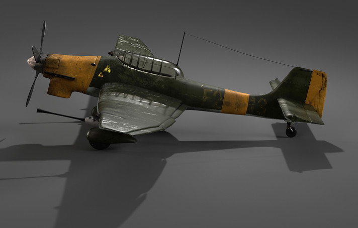

For the reference section of this project, I tried to stay near german style plane colors since the model is a german aircraft from WWII. I went with the green base and added the yellow markers to the front and tip to give it more pop. Trying to find damaged warplanes that have been shot at was very difficult because of how fast these planes break when getting shot at. They usually catch on fire and explode, not leaving much solid debris.
UV Layout

Here are the final UVs for the plane. The goal I wanted for this plane was to separate my section into color and material. I've been using this method as of late, which has been very helpful in laying everything out correctly in Mari. I made sure each tile had the same texel density and was laid out correctly over the plane itself.
Diving Into Mari


For the Mari section of this project, there are a couple of things I do before getting it ready. I take the model into substance painter, where I can bake out mesh maps for the object. I first grab the ambient occlusion and curvature maps to bake them into my project. I use Mari Extension Pack for texturing this whole plane, and the tool is an absolute blessing to have and makes working on complex models a breeze. The image above shows the basic setup of my tileable material creation. I would create regular materials and build a palette I can use on this plane and any other models I texture. The picture to the write of the material is the inside of the green plane paint material. I try to follow the same process through each material


Above are the materials I use on this plane! All of them were created in Mari and rendered out in Maya Arnold
First Renders

After I was done putting tileables on the teapot, I moved the materials over to the plane. I imported all of the materials into my Mari file to start layering on the specific sections. For the masking of the materials After layering the materials from above, I can start making bake points in Mari and import the maps into Maya to do the look development.


Here is a first pass of all of the materials laid out on the plane. From this section, after all of the materials are laid out, I attach a multi-channel bake point (the red node at the end) to bake down the material data, so my computer doesn't explode, lol. The multi-channel node can switch with each type pf shader you use in Mari. For this project, I stuck with making default Principle BRDF materials so I can take them into most cg programs.
Mask Generation

Before adding some of Mari's custom procedurals to the materials. I create some other custom masks such as dirt, dust, build up in crevices and wear on edges. I didn't have to make to many just because a lot of the detail that will be present on the plane will be manually painted on. Mari Extension Packs procedurals are a really good jump start to visualize what some damage on the plane will look like.


Texture and LookDev
In this part of the blog, I'm going to be going through the section and how I layered each to build the look I have now. After all of the materials combining, You can start working individually in each layer and slowly build up detail. I first started by adding displacement to the plane so I could see a better visual representation of cuts and dings, and dents. To begin, I went to quixel mega scans to pick up a weld tile material to lay on the plane to make it look like it's paneled together.
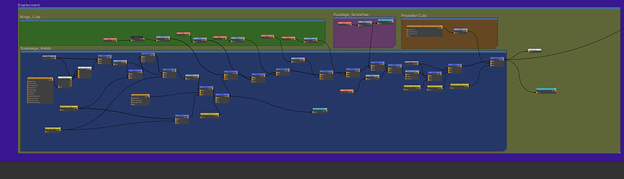
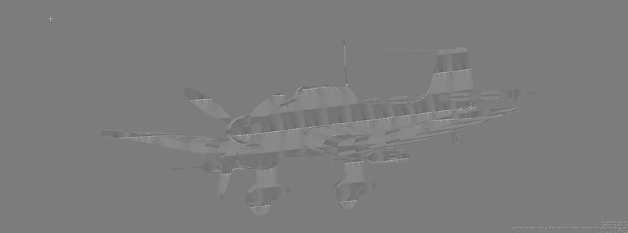
In this part of the blog, I'm going to be going through the section and how I layered each to build the look I have now. After all of the materials combining, You can start working individually in each layer and slowly build up detail. I first started by adding displacement to the plane so I could see a better visual representation of cuts and dings, and dents. To begin, I went to quixel mega scans to pick up a weld tile material to lay on the plane to make it look like it's paneled together.

I learned this method from Meshman Stusios on youtube. Since the displacement you acquire from Quixel is in the red channel, you have to convert it into a black-and-white mask and combine it with a float value, so the displacement is laid out correctly.


In these two screen shots, I wanted to remove the grain applied with the welds when making the image tileable. I stopped with the displacement at this point and saved a welding mask I made with the vector split. I did this with radio nodes that are provided with extension pack. It acts like a save point that you can transfer around the graph. I started a bump/ normal section of the graph to have that extra layer of texture and lighting detail on the plane.

I keep it in value for the time being because I can instantly convert it to normal information. Here I can layer the welding information, as well as other scratches and cuts I will add to the plane in the future. The bump is connected the same way as the other channels by having a single connection back to the layered materials.

Once the welds were applied correctly, I moved onto adding cuts on the wings to resemble bullet cuts. Mari has a nice feature of having intense bump placement. tweaking the valur of the bump while your painting displacment can give you more ideas of how to place cuts down.

once I get this working, I can then attach it to a displacement channel and export it into Maya so I can do a test render of the cuts.


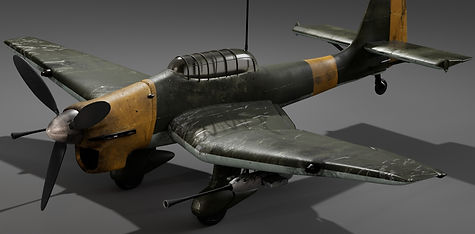
From the top left, reading left to right, are the renditions of the welds and scratches applied to the plan e. While working on the scratches, the radio node I have connected is collecting all of that information and applying it to the other sections, such as specular roughness and the base color.

After displacement is applied, it is plug-and-play from there. Using all of the previous material information, such as specular roughness, normal information, and displacement, I can add dirt and stains and adjust roughness as I see fit for the plane. I will be adding more information very soon on my process, I just need to grab some more photos and render to show everyone. Stay tuned!
Project Update
Hi everyone! It's been a little bit, but I wanted to update my process of the warplane. I have added some more decals to the surface of the plane. While talking about the decals, I am going to be breaking down the base color section of my node graph.
Like the other map connections of the node graph, I connect a merge node to my material connections and get a direct connection to the base color part of the plane. The first thing I do when laying the colors is to create more black-and-white masks like the ones I created for layering scratches and dirt. Those will be the section of nodes that are behind the wheel color box. Working this way allows me to select specific points of the plane and plug into a new layer of color by merging them over the next section. As I add further onto the base color, I start finalizing the plane as well with wrapping up little surface imperfections.

Within Mari, there is a plugin you can buy called the Mari extension pack. This pack allows you to save out node data at any point in your graph and use it in another area. Earlier in this blog, where I made the black and white masks for specific areas on the plane, I can connect a radio transmitter node to the masks, and put down a radio node(the yellow nodes) and add complexity to the textures pretty quickly Below are some process renders of slowly building up dirt along with decal wearing.


This was my favorite part of the project because of how easy it was to pick and choose the areas I wanted dirt, scratches, divots, and more! Learning this new workflow allows so much versatility in layering your textures, as well as makes building any asset's texture set easier.
When looking at the plane base color section of the graph, the biggest thing to notice is the mainstream of dark blue merge nodes going up the center. Using the extension pack radio nodes, I can call on specific areas of the plane, like the guns, and update the color or use other masks I have and isolate them to the guns and start texturing without affecting other parts of the plane. Once I am finished with a section, I merge the section into the main merge stream and use blend modes like in photoshop to apply each section in a unique way. At the end of the base color, I add the decals to the plane. Adding the decals was very easy. I used pre-existing colors on the plane to use as the decal colors. When adding the quadrant decals, I used inspiration from a bunch of different warplanes to make the decal. I projection painted the numbers and letters onto the plane, and then I would go back through with an eraser brush and slowly chip away at the edges and fade the paint away around the bottom and near the weld points on the plane. This same process is also applied to the white cross hatch marks on the wings.

To compare two different workflows that could've been used here, the first method could've been that when I was applying the decals, I could've used old masks for the welds and other parts of the plane and fed that information into my paint nodes so that it doesn't go over those areas. The second method is the one I ended up choosing, which is the eraser brush method to make dirt and wear more authentic in its application. I would use the under scratches as base points to make the paint wear on the wings unique to each side and try to have a sense of flow going through the damage to make it look like the force of wind also had an effect on the wear.